
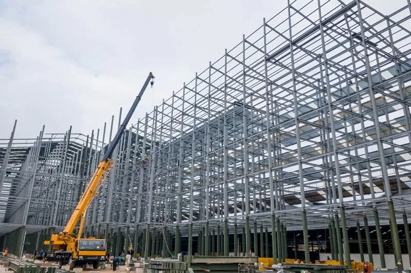
Mergen-Steel Profile Processing Center R&D Project
The most important of the steel building pre-fabrication stages is the cutting and drilling of single parts.
In this project, different solutions for the processing of steel profiles are proposed.
1-Current Situation
2-Problem Definition
3-Outsourcing steel plate and profile processing
4-Why the outsourcing steel profile processing is not possible today
5-Our proposed solution
6-Why Our 1D Nesting Method Is Unique
1-Current Situation
Detailer: The detailing of the steel building is done using software such as Tekla Structures or Advance Steel. From this model, single parts, assembly parts, cross-section and plan drawings required for manufacturing and erection are taken.
The purpose of using this type of software is that the production is one-to-one with the 3D model. This is only possible by using DSTV-NC files used by CNC machines.

Steel building manufacturer:
- Steel profiles are in a standard length at the material suppliers. Using the list of materials at hand and according to the standard profile length (usually 12m), a specialized and experienced engineer prepares the cutting plans.
- The purchase order is issued according to the quantity and stock length information obtained. After the steel profiles arrive at the factory from the supplier, the cutting and drilling process starts.
- In large manufacturers there are CNC profile cutting and drilling machine. These can perform precise and fast manufacturing using DSTV-NC files.
- Small manufacturers use band saws and vertical drills. The speed of the process is slow, the precision depends on the worker.
2-Problem Definition
In the cutting plans prepared using the 1D Nesting software available in the market, single parts are placed within the standard stock length (usually 12m), but if no splice is made, it causes a lot of scrap and remnant parts. Let’s illustrate this with a real example.

The cutting plan for HEB400 steel profiles, highlighted in yellow, for a stock length of 12.1 m without splices is given below. The following cutting plan consists of 1×4986 and 8 x5932 long remnant pieces.

It is often preferable to have a specialized and experienced engineer make the cutting plans by hand, as this results in a significant cost increase. The focus here is on minimizing losses. This requires making splice.
However, engineers often do not consider bolt locations and the welded part. Splices should be located away from these restricted areas. If the splice is in a restricted area, it creates problems in the quality control phase.
If we carefully examine the picture below, there are many plates and beams welded to the single parts of highlighted HEB400. The possibility of collision is quite high. It is really risky to make a cutting plan with splices.

The factory undertakes the quality responsibility by making a cutting plan with splice for steel profiles with its own machine. Depending on the chance, it may not encounter a problem. But generally, not…
If the project-specific stock length could be determined, there would be no need to make a splice. For this purpose, it is necessary to queue at the steel rolling mill and take the waiting time into consideration. However, in most countries this is possible for very high orders (500 tons) and 3-4 months waiting time is inevitable.
3-Outsourcing steel plate and profile processing
Outsourcing is a business practice in which companies use external providers to carry out business
processes that would otherwise be handled internally.
| Pre-fabrication work | Steel Building Manufacturer Size | ||
| Small | Medium | Large | |
| Plate cutting and drilling | outsource | outsource/ CNC Plasma | CNC Plasma |
| Profile cutting and Drilling | manually | manually | CNC Machine/Line |
What would change if steel profiles cutting and drilling with CNC machines could be outsourced?
• The single parts would exactly match the 3D model. (High quality)
• The single parts could be produced very quickly (100 ton/day)
• There would be no need to invest €1~2M to buy a CNC machine
• There would be no need to build a new building for this machine and buy land for this building.
(Today, the cost of a 2000m2 facility in industrial zones in Istanbul is not below €2M.)
Take a medium-sized manufacturer with a monthly production capacity of 1000 tonnes
At least 15% of the employees work in profile drilling and cutting. If we assume that there are 600
employees, there would be 90 workers.
• Employee cost reduction (there would be no need to employ 90 workers.)
• If we assume that the employee monthly costs are €3000/month, €270k/month savings can be
achieved.
• If this company pays €250/ton for outsourcing profile drilling and cutting work, there is a cost of
€250k/month. Outsourcing cost is less (250<270).
Medium and large-scale companies can create serious resources for themselves by outsourcing this
work (saving workspace and cutting and drilling line cost). – – –
They can reduce the cost of the welder by buying welding robots with what they earn from
here.
This reduces the need for a welder by at least %50 (approx. 150 welders)
In addition, there are no problems in the quality control phase as welding defects are
significantly reduced.
| Therefore, outsourcing of steel profile and cutting works is very beneficial. In this way, it is possible to turn into a more efficient manufacturer. |
4-Why the outsourcing steel profile processing is not possible today
Large fabricators produce complex structures with large steel buildings. This can be a refinery plant or a
cement factory or a multi-story structure


If no splice is made to the cutting plans, a large number of remnant parts will be produced. This is not a
valid solution, as these remnant parts would cost the customer a lot of money. No customer will accept
this solution.
Cutting plan without using splices (10 x 12100mm)
As shown in figure below, it is possible to reduce the required number of stocks from 10 to 6 by making splices. But in this case, the splice location should be checked for bolt holes or other welded parts. A 3D model of related structure is needed for this. It is much bigger and more complex than one might think.

Cutting plan using splices (6 x 12100mm)
In the above-mentioned large projects, especially in petrochemical plants, there is a very serious supervision. Splices in inappropriate places create problems. Faulty production is not tolerated. Large fabricators do not trust any outsource company that has no knowledge of the steel structure project.
| The splices in the wrong places create big problems. There is no company that can take this responsibility and guarantee that the splices will be in the right place. |
5-Our proposed solution
- If a steel profile supplier sets up a facility that provides profile cutting and drilling services, could this be a solution?
- Can the software we have developed solve the problems of this service?
- Will this service increase the sales of the steel profile supplier?
- Could this be a profitable investment?

In the activity diagram above, small and medium size manufacturers who do not have CNC profile cutting and drilling machines are taken into consideration.
In the facility, which we call the profile cutting and punching center, only H-shaped steel profiles used as columns and beams will be processed.
a. The Tekla model is checked repeatedly for manufacturing using DSTV-NC Because the manufacturing will be done using these files and it is not possible to go back.
b. After the cutting plan with splice is prepared, the biggest problem is to check the suitability of the splice location. The easiest method for this is to put the splices on the 3D model of the structure and test the collision over the image. The 3D model of the structure can be obtained with an IFC file. Mergen uses the information in the DSTV-NC and IFC type file.
c. In the following cutting plan, the single parts used in the cutting plan prepared in the previous section are used. The difference compared to the previous one is that this time, splicing is allowed in the 1D Nesting algorithm.
Cutting plan without using splices

Cutting plan with using splices
The cutting plan with splices is quite successful. Previously it was necessary to use 10 x 12100, now 6 x12100 mm is sufficient.
When determining the splice locations, the following settings were used;

- Standard Stock length 12100mm
- 20mm cut at the ends of 12100 mm stock (Edge cut distance)
- Saw width is 3mm
- Splices can be made at least 250mm away from the bolt group and welding contours
- Minimum length of the part to be spliced is 2000 mm
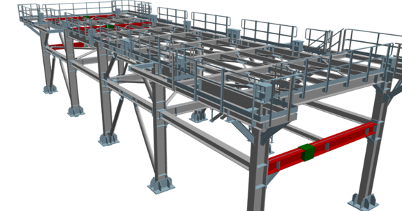
But is the location of the splice good enough? For this, let’s examine the 3D model pictures below. The red color represents the spliced beams and the green rectangular prisms show the location of the splice.
d. In the above shown activity diagram, it is mentioned that in some countries it is possible to order special sizes for the steel rolling mill. In the following user interface, the optimum stock length between 10,000-14,000mm is investigated. There is a cutting plan without splice by using a stock size of 5 x 13,750mm.
It is often inappropriate to wait 3-4 months for a job of this amount (Total ~68m).


e. If the cutting plans are suitable as seen from the 3d model above, the steel structure manufacturer will also approve
f. Mergen can produce a DSTV-NC file specific to cutting length for the parts to be obtained with splice. From now on, according to this cutting plan, it is possible to drill and cut this individual part using the DSTV-NC files we have.
g. Afterwards, quality documents will be prepared and ship to the steel structure manufacturer.
| The software we have developed (Mergen) can solve the problems of this service |
6-Why Our 1D Nesting Method Is Unique
- What makes this software special?
- 1D nesting software has been on the market for more than 30 years. Can’t it be done using them?
In current market there are many 1D Nesting software
- 1D Nest
- OptiCutter
- Real Cut 1D
- Nest 1D
- 1D Stock Cutter
- CutLogic 1D
- PLUS 1D
- Optimumcut-1D
- FastCUT
- Pro
- 1DCutX
a. Ability to create a cutting plan with splice can reduce material requirement.

Cutting plan without using splices (10 x 12100mm)
This cutting plan can be obtained with the software listed above. As can be seen, there are a large number of remnant parts. It is not possible to get better than this.
Steel structure manufacturers are not aware of such problems arising from cutting at the contract stage with the customer. The company will try to utilize the remnants from the cutting plan in its warehouse until the next job. In order to avoid this situation, it is absolutely necessary to make splices.

Cutting plan using splices (6 x 12100mm)
Making a cutting plan by making splices significantly reduce the amount of material. Unfortunately, it is not possible to make a seam at every desired point.
b. Make splices away from prohibited areas with bolt groups and welded parts,
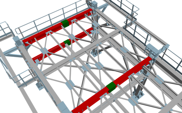
The red color indicates the single parts to which the splice has been existed. Where there are green prisms, a splice has been made.
c. Obtaining parts longer than the standard length by splicing stocks.
Sometimes detailer can model much longer steel columns and beams, especially steel columns and beams, even though they know that the standard stock length is 12m. This feature has been developed to solve such problems.
d. Keeping records of remnant parts with the inventory management module
In particular, the priority of the top managers in the factory is to utilize the remaining parts in the warehouse. A simple warehouse management module has been developed for this need.
e. Prioritized use of remnant parts in the warehouse,
Pieces of remnants found in the warehouse are firstly utilized. Thus, these steel profiles do not have to be scrapped or their costs are not passed on to the customer.
f. Easy approval for the cutting plan with splices by showing the location of the splice on the 3D model

Seeing the location of the splices to be made on the 3D model and seeing that it does not cause a conflict, especially with bolt groups and welded plates, makes it easier for the steel structure manufacturer to get approval from the customer.
For these splices, the structural engineer can get support from the structural engineer, or he can open a welding bevel and butt weld the parts to be joined with the splice. In this case, NDT tests will be needed.
g. Generate DSTV-NC files of split parts for the single part (1) to be obtained by splicing.
Tekla produces one DSTV-NC for each single part type. However, for parts that are spliced together, the operator must modify this part’s NC file. This requires a skillful and careful operator. Mergen can do this automatically.
